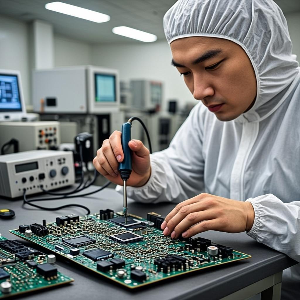
Ceramic PCBs have one ceramic substrate, and the copper layers are sputtered, plated, sintered, or brazed on the top and bottom sides of the ceramic substrate.
According to the different ceramic materials, there are AlN PCBs, alumina PCBs, SiC PCBs, Si₃N₄ PCBs, BeO PCBs, and hybrid ceramic PCBs.
According to the different ceramic PCB manufacturing processes, there are LTCC, HTCC, DPC, DBC, thick-film, thin-film, and AMB PCBs.
In ceramic PCB fabrication, PCBONLINE adopts two different lamination methods according to specific requirements.
Normal lamination: In the ceramic PCB lamination process under high-temperature and high-pressure conditions, two ceramic substrate layers are bonded by a dielectric layer (PP). The PP materials are mainly phenolic, epoxy resin, and special thermal conductive materials. Sintering lamination: In the PCB lamination process under high-temperature and high-pressure conditions, molecules of the two ceramic substrate layers' contact surfaces migrate, and the two layers integrate and form dense polycrystalline ceramics as a whole (relative density > 98%).
The normal lamination process's manufacturing cost is low, but it drastically reduces the overall thermal conductivity of the ceramic circuit board, and its bonding strength is not as good as sintering lamination.
If the PCB requires high thermal conductivity, we use the sintering lamination method. This technology bonds the copper and the ceramic material together with a strong bonding force and high reliability. Meanwhile, the characteristics of the ceramic substrate are not affected, especially the thermal conductivity and flatness.
DPC is one of the ceramic circuit processing technologies at PCBONLINE. It developes from the thin-film PCB manufacturing process.
The DPC PCB process includes ceramic surface metalization, sputtering, copper plating, film exposure and development. Its ceramic PCB manufacturing flow is:
Compared with the thick film and thin-film processing technologies, the DPC technology provides faster processing, a micron-rating fine process, and no ceramic type and thickness limit.
PCB depaneling is the step of removing single ceramic PCBs from the entire panel. At PCBONLINE, depaneling after the ceramic PCB fabrication or assembly can be laser-cut or diamond-cut. (V-cut and CNC can't depanel ceramic PCBs.)
PCBONLINE suggests designing the ceramic PCBs as rectangular or squire as possible. But round ceramic PCB manufacturing is okay for PCBONLINE. We provide professional engineering support to your project to penalize your ceramic PCBs and avoid carbonization.
Applications of ceramic PCB: