In the automotive intelligence, electrification process accelerated today, automotive electronic circuit boards PCBA as the core carrier of the automotive electronic system, the processing process is precise and complex, any one of the links are related to the performance, reliability and safety of automotive electronic equipment. This article we will give you a detailed introduction to the electric car pcba assembly process, all-round control of the quality of electric car pcba.
PCB is the backbone of electronic equipment, providing a physical platform for installing and interconnecting various electronic components. In electric vehicles, pcb has a wide range of uses, including.
Circuit board substrate procurement: first of all, according to the specific needs of automotive electronics, select the appropriate circuit board substrate materials. In view of the harsh environment inside the car, large temperature changes, strong vibration and electromagnetic interference, usually with high heat resistance, high mechanical strength, good electromagnetic compatibility of the substrate, such as special modified FR-4 board or high-performance flexible board. These substrates should meet strict industry standards to ensure stable operation under complex working conditions.
Selection and procurement of electronic components: According to the design of the automotive electronic circuit, we accurately screen all kinds of electronic components, including resistors, capacitors, inductors, chips, etc. The quality of the components directly determines the quality of the PC. The quality of the components directly determines the quality of the PCBA, so we must use products that meet the automotive-grade standards, with high reliability, wide temperature range adaptability and other characteristics. Purchased components need to undergo strict factory inspection to check the integrity of the appearance, the accuracy of the electrical parameters, to prevent defective products from entering the production line.
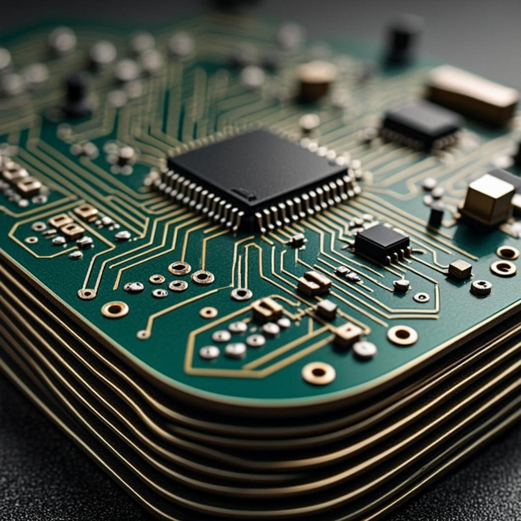
Solder Paste Printing: Solder paste is printed onto the circuit board pads through high-precision stencils to ensure sufficient quantity and accuracy to avoid soldering defects. The stencil is laser cut or etched, and different pads correspond to different mesh holes in order to meet the packaging requirements of the components.
SMD: The components are quickly and accurately mounted onto the pads using high-precision mounting machines to ensure that tiny components such as 0201, BGA chips, etc. are accurately aligned and pasted with solder paste.
Reflow Soldering: After the placement is completed, the temperature profile is precisely controlled through a multi-temperature zone reflow oven to ensure that the solder paste melts and solidifies uniformly, forming a high-quality solder joint, avoiding damage to components, and ensuring the reliability of the soldering.
Some of the automotive electronics PCBA also involves through-hole technology (THT) processing link. For some larger power, high mechanical strength requirements or not applicable to SMT components, such as large electrolytic capacitors, relays, etc., need to use THT technology.
Insertion: Workers will insert the pins of the components into the pre-drilled holes in the circuit board, requiring the insertion of the right depth, straight pins, to ensure a good connection with the circuit board and the inner layer of the line. This process requires manual operation combined with auxiliary tooling to ensure the accuracy and consistency of the plug-in.
Wave soldering: After the plug-in is completed, the wave soldering equipment is utilized for soldering. Liquid solder to form a wave-like shape, the circuit board from the wave through the peak, so that the component pins and circuit board pads are fully infiltrated welding. The key to wave soldering is to control the solder temperature, wave height and soldering speed to ensure that the solder joints are full, no false soldering, while avoiding short circuits and other problems caused by too much solder.
Appearance Inspection: Comprehensively inspect the PCBA appearance, check the missing components, offset, damage and defective solder joints and other issues, with the help of magnifying glass and other tools to ensure the quality of the appearance, to avoid potential safety hazards.
Electrical performance test: use professional equipment to test the PCBA electrical parameters, to confirm that the circuit connectivity, power module output and signal integrity in line with the design requirements.
Functional test: simulate the actual automotive environment, verify the actual working performance of PCBA through the test tooling to ensure its stable and reliable performance under various working conditions.
Considering the complexity of the automobile driving environment, automobile electronic PCBAs usually need three-proof (moisture-proof, mildew-proof, salt spray-proof) treatment. Special three-proof paint is used to form a protective film on the surface of PCBA by spraying, dipping or brushing to isolate the external moisture, mold, salt spray and other unfavorable factors and prolong the service life of PCBA.
Thermal Management: The power electronics in electric vehicles generate a lot of heat. To prevent overheating, manufacturers need to use high thermal conductivity materials (e.g. copper, aluminum substrates) and advanced cooling technologies (heat sinks, hot channels, liquid cooling, etc.), and manage the coefficients of thermal expansion between different materials to avoid damages triggered by temperature changes.
High reliability: EVs are often exposed to harsh environments such as vibration, temperature differences, moisture and dust, and PCBs must be highly reliable and durable. Manufacturers need to follow IPC standards (e.g. IPC-A-600, IPC-A-610) and take protective measures such as conformal coating and encapsulation, and perform rigorous testing (temperature cycling, vibration, humidity, etc.) to ensure quality.
Miniaturization: PCBs are becoming increasingly miniaturized to fit compact vehicle designs, using HDI technology for microfabrication and multilayer stacking. Precision assembly and 3D PCB design software ensure compact layouts and stable signal and power distribution.
High power density: The high power requirements of electric vehicles require PCBs that support high currents, using thick copper layers and wide alignments to ensure stability and minimize losses in the power layer. Effective grounding, shielding, insulation and safe distance design are also critical to ensure safety and EMI suppression.
Cost and Scalability: While pursuing high performance, manufacturers need to control costs and increase production flexibility. Automated production (e.g., AOI, SMT) can reduce labor costs and improve consistency. However, there is still a need to balance innovation, cost and scale in the context of rapidly evolving technology.
Compliance with industry standards: Manufacturers must follow industry standards such as ISO 16750, IPC, and others to ensure that PCBs meet requirements for safety and performance. Compliance requires complete documentation, validation and process adjustments to adapt to changing regulations.
The future of EV PCB assembly is bright, and the following trends are driving change in the industry:
LST specializes in automotive electronic circuit board PCBA processing field, with advanced production equipment, from high-precision solder paste printing machine, top-class mounter to precision reflow oven, professional testing instruments, to ensure that each processing step can meet the automotive quality standards. The company’s technical team is experienced and familiar with the automotive electronics industry specifications, providing one-stop PCBA processing services. At the same time, strict quality control system throughout the production process, through multiple rounds of testing and debugging, to ensure the delivery of each piece of automotive electronics PCBA has a high degree of reliability, for the booming development of the automotive industry escort.