Sunsoar Tech is a professional printed fast circuit board manufacturer. The production base is located in Baoan, Shenzhen. After years of continuous innovation and development, it now has a PCB Division and an FPC Board Division. Its products are widely used in communication equipment, automotive electronics, computers, medical equipment, network equipment and consumer electronics.
We have 13 years of experience in PCB production. Our current factory covers an area of 10,000 square meters, has 10 production lines, and exports to more than 100 countries. All our substrates and processes comply with ROHS and UL international certifications, providing 100% quality assurance and customer service commitment.
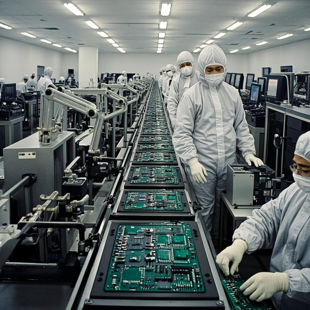
The professional purchasing team is able to purchase domestic and foreign components to ensure the best quality and competitive prices, and the professional engineering team is responsible for burning procedures and testing to ensure that the products meet customer requirements. We provide one-stop service from sourcing, manufacturing, assembly to customized packaging.
We have multiple advanced equipment for PCB assembly, such as high-speed SMT machines, multi-function SMT machines, 12-wet HALS lead-free hot air reflow machines and ICT testing machines, etc., which can quickly complete surface mount, through-hole and BGA, QFP, QFN, SMT, PTH and other parts assembly.
The strict quality system requires AOI testing (BGA package X-ray) for each board, including first article inspection before SMD process and first article completed sample before DIP process. And through IQC, IPQC, OQC, spot inspection and other methods to ensure high-quality output of products.
Flexible PCB technology, also known as FPC (Flexible Printed Circuit), is continuously growing, with applications in the main electronics sectors, such as consumer, automotive, electro-medical devices, wearables, telecommunications and aerospace. The introduction of flexible PCBs has revolutionized the legacy electrical interconnection techniques, traditionally used to connect multiple parts of the same circuit or of multiple electronic devices. Thanks to the flexible nature of the connection, its compactness, and the high density of electrical connections that can be achieved, the solution based on flexible PCBs allows to obtain a considerable reduction of space, weight and costs compared to an equivalent solution based on rigid PCBs. Flexible printed circuits have replaced many types of wiring, often done by hand, in several applications, reducing the total cost of electrical wiring by up to 70%. The heart of an FPC is represented by flexible films and thin layers of conductive material that make the electrical connection by replacing the traditional wires (think, for example, of the connection between a microcontroller board and an LCD or OLED display), and on which electronic components can be directly attached via soldering or conductive adhesive. Figure 1 shows an example of flexible printed circuit.
As the name suggests, these PCBs are a hybrid of flex and rigid PCBs, and they combine the best of both configurations. Typically, a rigid-flex PCB configuration features a series of rigid circuits that are held together using flex circuits. These hybrid circuits are in demand because they allow designers to improve the capability of their circuits. In these circuits, the rigid areas are mainly used for mounting connectors, chassis, and several other components. However, the flexible areas assure vibration-free resistance, and are flexible. Thus, various advantages offered by these circuit boards are being exploited by PCB designers to produce creative circuit boards for challenging applications.
HDI is an abbreviation for high density interconnect. These PCBs are perfect for applications that demand higher performance than regular flexible PCBs. HDI flex circuit boards are designed incorporating several features such as micro-vias and they offer better layout, construction, as well as designs. HDI flexible PCBs utilize much thinner substrates than regular flexible PCBs, which helps reduce their package sizes as well as improves their electrical performance.
This is one of the basic types of flexible circuit boards comprising a single layer of flexible polyimide film with a thin layer of copper. The conductive copper layer is accessible from only one side of the circuit.
As the name indicates, these flex circuits are single sided, however, the copper sheet or the conductor material is accessible from both sides.
These circuit boards feature two layers of conductors on each side of the base polyimide layer. The electrical connections between two conductive layers are made using metalized plated through holes.
A multi-layered flex circuit board is a combination of several double-sided and single-sided flexible circuits. These circuits are interconnected through plated-through holes or surface mounted in a cohesive pattern.
1
2
3
4
5
6
7
A PI or PET substrate is the core of an FPC. The PI material is typically yellow, and the PET substrate material is transparent.
The copper foils are the circuit layers of a flexible PCB. RA copper is rolled annealed copper. It requires adhesive in flexible PCBs. ED copper is electrolytic copper. It doesn't require adhesive layers in an FPC. Thick-copper PCBs (3oz) must use RA copper.
Stiffeners are rigid connectors laminated at the end of flexible PCBs for connection with the system/device interfaces. Stiffeners are optional for flexible PCBs. There are FR4 stiffeners, PI stiffeners, and stainless steel stiffeners.
It is crucial to comprehend two aspects of bendability: how frequently the board will flex and the extent to which it will flex. Whether the PCB is static or dynamic depends on how many times it can bend. A static board will flex less than 100 times in its lifespan and is regarded as bend-to-install. Mostly, it is bent while being assembled. The design of a dynamic board must be more durable because it bends frequently and must be able to resist thousands of bends. The flex circuit’s flexibility is directly impacted by its thickness. The more pliability, the thinner the material must be. These boards’ thickness varies depending on a number of variables:
Includes consumer products, some computer and computer peripherals suitable for applications where cosmetic imperfections are not important and the major requirement is the function of the completed printed board. Requires minimum inspection, testing, and performance standards. Applications include disposable electronics.
Includes communications equipment, sophisticated business machines, instruments where high performance and extended life is required and for which uninterrupted service is desired but not critical. Requires medium inspection, testing, and performance standards. More expensive than class one, the applications of these boards include cameras, smartphones, and medical diagnostic equipment.
Includes equipment and products where continued performance on demand is critical. Equipment downtime cannot be tolerated and must function when required such as in life support items or flight control systems. Printed boards in this class a