Over recent years, there has been the notable advanced development of technology. One of the most appreciated adjustments is in the circuitry field. Flexible Printed Circuit Boards manufacture is one of the major achievements in this sector. Indeed it’s this gadget that has since replaced the need for hand built wire connections, connectors, and harnesses. Now, this guide is solely meant to enlighten you on all the arising issues about this circuit. Stay alert and read till the end.
To kickstart our discussion, consider this. Which kinds of electronic appliances do you use? I suppose they include smartphones laptops, computers, digital Televisions, phone tablets, cameras, and any other gadget.
Have you ever wondered about what kind of connections they use? Now, this interestingly brings us to the main course. Flexible PCB is simply a device used in electrical connection simply made by the advanced technology of assembling various electronic circuits, connectors and good electric conductors (copper) into a single unit film base usually a dielectric material.
They are distinctively thin, easy to bend due to their flexibility hence can be light and small in size. These qualities make them a popular brand among users. Rapidly, the flex PCB are substituting the conventionally built hand wires connections and connective boards. That’s was the sole purpose for designing these PCB’s initially. One might be thinking if indeed there exist rigid PCB since we got the flexible one. Absolutely, your guess is right. Importantly, flex PCB is also known as flex circuits or flex printed circuits. We shall, therefore, use these synonyms interchangeably. Flex PCB circuits are distinctively designed and fabricated. Now this where most designers go wrong, most tend to design the flex circuits in a manner that is similar to the design guidelines of circuit boards. Note that the Flex circuits are different from circuit boards. Let’s consider this phenomenal – What is the reason for naming Flex circuits as “printed’? It’s simple! A common manufacturing process involves printing the circuits design. However, due to the recent upsurge in technology, most designers photo or laser image as a better method instead of printing.
So the two types of PCB’s are:
The only design difference between these two types of circuitry lies in their adaptability and usability. Basically, the rigid PCB can’t be twisted or transformed into varied shapes, unlike the flexible one.
Among the lists of electronic gadgets mentioned above at the start of our discussion, the rigid PCB is employed in the laptop, TV’s, desktop computers, audio keyboards among other numerous devices. Elsewhere, Flex circuits boards are usually incorporated in highly sophisticated or technical devices which requires extreme accuracy. Flex circuit boards are incorporated in digital cameras, smartphones, GPS devices, satellites, hearing aids, heart monitors and digital calculators etc. Interestingly, the rigid and flex circuits could be used together in a single device to provide an outstanding result. Since our discussion is purely based on Flex circuits, we end the comparison of the two and proceed to an important segment of our discussion.
The flex circuits are have got several benefits compared to other conventional electrical connections. Unlike the cables and rigid boards, the Flex PCB boasts of:
Clearly, Flex circuits deserve the lead and praise among the connectors. Don’t you think so? If not satisfied, let’s have a look at a comprehensive benefit of Flexible Printed Circuit Boards.
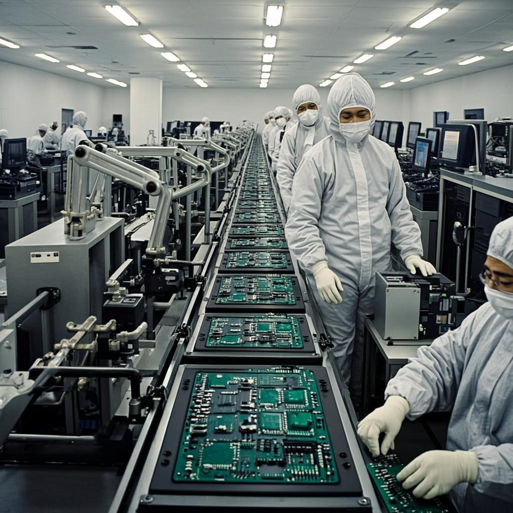
The flex production involves automated and technologically advanced machines. This makes the building process to be efficient and eliminating several production faults which may occur. Conversely, these errors are prone in the manually designed wires and cables.
This doesn’t mean that Flex circuits are faultless. There may occur some machine-related errors though insignificant. Due to this kind of production technology, the several circuits are only attached to the rightly designed positions.
An outstanding feature of flex assembly is that it doesn’t really require a lot of manual labor for construction just simple and easier processes summarizes the whole technique. Full interconnection systems are installable or replaceable rather than the whole each board.
All these reduce any chances of manufacturing errors from wiring and eventually minimizes the costs that may be incurred in continued connections. Flex circuits also don’t really involve other subsidiary mechanical processes such as soldering, wrapping, and parts routing which are quite costly. In totally, no matter the volume of production of the Flex circuits, you are absolutely sure of savings in costs and time efficiency.
Have you ever tried to create shapes and designs by twisting flexible material like a rubber band? How many configurations would you achieve? Uncountable right?
A major feature of Flex is its’ ability to assume a three dimensional configuration as opposed to the restricted two dimensions of the rigid boards. This a major feature prompting designers to switch their focus to flex circuits. So, this kind of flexibility makes the circuit to possess endless designs and forms just like the numerous options available when working with ribbons. These forms range from highly complex to simple configurations. Significantly, they are tutored to promptly function in up to hostile conditions. Some of the common flex circuit designs are:
This is also another main benefit of working with flex circuits. During execution, they can be used with another element since these circuits can interconnect among planes.
Therefore, they only need limited space apart from their increased reduction in weight. In summary, these circuits can be maneuvered severally when installing but they never experience any electrical break down.
Flex circuits provide room for the numerous tiny lines. This would, therefore, lead to the production of high-density gadgets.
The indisputable advantage of this mechanism is the fact that this denser device and lightweight conductors may be designed into a commodity. This allows the creation of space for setting up the product’s features.
Uniquely, flex circuits are capable of moving and twisting for numerous cycles without any damage caused as power and signal is sufficiently delivered without any lapse. This is a feature found in the devices that have got the moving parts. It doesn’t also suffer from thermal effects. Why? Because it’s made of polyimide which has got excellent heat resistivity.
Other advantages due to this are:
In cases of extreme vibrations or unnecessary acceleration, flex PCB effectively limits impact on itself. Why so? Flex circuits have got ductility and little mass.
Let’s do some little math. A tiny object does have a large surface area to volume ratio. Flex PCB isn’t an exception. Additionally, it is compactly designed. All these features ensure a small heat path is designated. Moreover, the flex design can thermally regulate heat from both of its sides ensuring sufficient heat loss.
The dielectric in the flex circuit is extremely thin which contributes to the streamlined shape thus no bulky components would be required. Actually, a single flex circuit would essentially substitute several cables and connectors.
Latest experimental records report that flex circuits help in sparing about 75 % of the space available thereby creating room for other wiring procedures. The package size is highly limited since Flex PCB is highly flexible and elastic. Importantly, the package weight is another feature that is greatly minimized.
The flex circuits receive adequate air circulation due to their streamlined shape which in turn assists in cooling down the components of the machine.
The more complex and simplified patterns that were unimaginable difficult to implement in the rigid boards have been made possible thanks to flex circuits.
In fact, some recent technologies places surface mount electronics straight onto the circuit. The pros of this technique make the design more reorganized and simpler.
One major defect of the olden circuits was failure resulting from the interconnection points. This a major defect related to cable wiring. Thanks to Flex circuits, this problem is well catered for since these interconnection sections are greatly minimized which enhances the reliability of the circuit. Now, you may want to reflect on these gains of using flex circuits. I surely trust that you’re now convinced of the needs of implementing flex circuits as opposed to other traditional circuits. Shall we go on?
These devices are made from different components from simple locally available resources to other special kinds of substances. The four main materials are:
Note that flex circuits may be made from a variety of numerous materials. The main considerations made when selecting the materials to be incorporated in the manufacture are:
Why don’t we now specifically discuss each item?
These include all the other materials that are used to cover the conductor material. The reason behind this is quite straightforward. Although copper is an excellent conductor of electricity, it has one limitation, copper easily oxidizes resulting in the formation of a thin layer on its surface. For this reason, the exposed copper surfaces are covered using substrates and cover overlay materials. The two common materials used to do this are gold or solder.
These two materials are preferred due to their two main physical properties i.e good conductivity and durability when exposed to the environment that is the ability to resist rusting.
Since we’re dealing with electricity here, the main conductor material extensively used in Flex circuits is copper. However, copper is modified into different thicknesses suitable for each customer’s needs. Copper is recommended since it offers value for money, meaning copper is cost effective. The table below summarizes the different types of materials used and their corresponding thicknesses.
Other conductor materials may include: