Flexible PCB is also called flexible printed circuit board, flex circuit, or flexible wiring board. As the name shows, it is a kind of circuit board that bends. It can fold, roll, stretch, and move in three dimensions. Flexible printed circuit boards are made on a thin film like polyimide or polyester. They give high reliability and very good flexibility.
Flexible printed circuits (FPC) trace their origins back to the 1950s, when researchers in the United States developed techniques to print and etch flat conductors onto flexible substrates as an alternative to traditional wiring harnesses.Makers used polyester or polyimide film as the base. These films make the board strong and bendable. By embedding circuits on thin plastic sheets, many small parts can be stacked in tight spaces. The result is a circuit that can bend, fold, and fit into compact shapes. Flexible circuits are light, take little space, cool well, and are easy to mount. They solved limits of old connection methods.
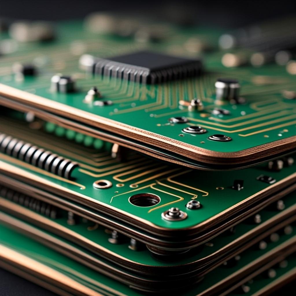
A flexible printed circuit board showing bendable structure.
A flexible circuit has three main material groups. First is the insulating film. Second is the conductor. Third is adhesive. These parts work together to meet the need for smaller and mobile electronic devices. Flexible circuits let devices become denser, smaller, and more reliable.
The insulating film forms the main base layer for the circuit. Adhesive is used to bond copper foil to the insulating film. In multilayer flex designs, the film is also used to bond inner layers.
The insulating film protects the circuit from dust and moisture. It also reduces stress when the board bends. The conductor layer is made from copper foil.
Some flex circuits use rigid parts made from aluminum or stainless steel. These rigid parts give dimensional stability. They give physical support for parts and wires. They also reduce stress. Adhesive bonds the rigid parts to the flexible circuit.
Another common material is a bonding layer that coats both sides of the insulating film. This bonding layer gives insulation and helps join layers. It can remove the need for some film layers and lets manufacturers bond many layers with fewer parts.
There are many insulating film types. The most used are polyimide and polyester. About eighty percent of flexible circuit makers in the US use polyimide film. About twenty percent use polyester film.
Polyimide is not easy to burn. It keeps its shape, resists tearing, and can stand soldering heat. Polyester, also called PET (polyethylene terephthalate), has physical traits close to polyimide. It has a lower dielectric constant and absorbs less moisture. But it does not resist high heat as well. Polyester melts at around 250°C and has a glass transition temperature (Tg) of about 80°C. This limits its use in products that need heavy board-edge soldering. In low temperature uses, polyester can act stiff. Still, polyester is good for phones and other products that do not face harsh conditions.
Polyimide films are often paired with polyimide or acrylic adhesives. Polyester films usually pair with polyester adhesives.
Rolls of PI film, a common base material for flexible circuits
Copper foil is a good fit for flexible circuits. Copper foil can be made by electro-deposition (ED) or by rolling and annealing (RA). One side of ED copper is shiny. The other side has a matte process surface. ED copper is bendable and can come in many thicknesses and widths. The matte side of ED copper often gets special treatment to make it stick better.
RA copper is both flexible and smooth. It can be stronger. RA copper is useful in designs that need repeated bending or dynamic flex.
Copper foil roll being slit for flexible PCB production.
Adhesives do more than bond the insulating film to the conductor. They can act as cover layers, protective coatings, or overlay layers. The main difference is how the layer is applied. The cover layer bonds to the insulating film and forms a laminated structure.
Screen printing is used for adhesive coverage and coating. Not all laminated structures use adhesives. Adhesive-free laminates make thinner, more flexible circuits. They also offer better heat transfer than adhesive-based laminates. Because there is no adhesive layer to block heat, heat moves through the circuit better. This lets adhesive-free flex operate in conditions where adhesive-based flex might fail.
Below are practical steps for hand soldering a PQFP chip and common SMD parts on flexible circuits. Use these steps as a clear guide. Follow safety and ESD rules too.
Flexible PCB with components soldered during assembly process.
Rigid PCBs are what people usually think of as circuit boards. They use conductors and other parts on a non-conductive board. The non-conductive board often contains glass. The glass makes the board strong and stiff. Rigid PCBs give good support for parts and good heat resistance.
Flexible PCBs also have conductive traces on a non-conductive base. But the base is flexible, like polyimide. A flexible base lets the circuit bend, handle vibration, cool well, and fold into many shapes. Because of these shapes, flex circuits are now common in compact and new electronic designs.
Besides the base material and stiffness, other big differences include:
Both types can work in many products. Some uses benefit more from one type. For example, rigid PCBs make sense in larger products like TVs and desktop PCs. Compact products like phones and wearables often need flex circuits.
When you choose, think about:
If your device needs folding, bending, or space saving, pick flex. If you need low cost and high mounting strength for large parts, choose rigid.
Stiffeners are also called reinforcement plates, support plates, or strengthening ribs. They are used in electronics to control flex. Stiffeners solve the problem that flex boards can be too bendy. They make plug-in areas stronger and help assembly.
Flexible printed circuit board featuring a stiffener to enhance mechanical stability during assembly
Common stiffener types:
Handling rules for polyimide (PI) stiffeners:
The neutral bending axis of a flex circuit may not be centered in the stack. Proper handling helps stop dents and cracks.
Flexible PCBs are like mechanical parts as well as electrical parts. The trace layout must make the whole circuit strong. Unlike a rigid board, a flex board can bend, twist, and fold to fit inside the final product. If the bend goes beyond a point, the copper is put under strong tension. That can break the flex or make dents.
Flex gives designers options that rigid boards do not. Even when flex is right for the job, that does not mean copper traces will never fail. Copper also has limits on the stress it can take.
You need to watch many things, especially when the product will see dynamic bending (bending while in use) or when it must fold into small housing spaces. Precision is important to avoid crack.
Flexible printed circuit board demonstrating bend and fold design considerations
Below are clear design ideas to increase life and reliability.
Know the limits for bending, folding, and twisting. For single-sided flex, if the stretch or squeeze exceeds the bend radius or stress point, the copper will crack. Always work inside these limits.
For dynamic flex use, single-sided flex designs are best. Single-sided gives the copper room to sit near the structure center. In this layout, the copper is not strongly compressed or stretched during dynamic bending.
Thinner stacks bend more easily. They have a smaller inner bend radius and less stress on the outer layer. For parts that bend a lot, use thinner copper and thinner dielectric layers.
I-beam means copper or dielectric layers overlap directly on both sides. This makes the fold area stronger. Because the inner layer compresses, the outer layer sees more stretch. To reduce this, offset the traces on opposite sides.
Many flex boards are designed to fold. A well-made board can take the first fold or twist. But repeatedly folding a creased area is not good. The copper will break over time. It is not recommended. Use design tricks like rounded corner traces in the fold area.
Other tips to avoid cracking:
Flexible circuits are popular in many products: