If you’ve ever worked on a pacemaker, patient monitor, or diagnostic imaging system, you know the stakes are different. A medical PCB isn’t just another circuit board—it’s the backbone of equipment that keeps people alive. After 15 years of designing boards for healthcare applications, I can tell you that getting this right requires understanding both the technical demands and the regulatory landscape that governs our industry.
This guide covers everything engineers and procurement teams need to know about medical PCB design, manufacturing, and assembly. Whether you’re developing a Class II glucose monitor or a Class III implantable defibrillator, the principles here will help you build boards that perform reliably when it matters most.
A medical PCB is a printed circuit board specifically designed and manufactured to meet the stringent requirements of healthcare applications. Unlike consumer electronics where occasional failures might be inconvenient, medical PCB failures can directly impact patient safety and clinical outcomes.
Medical PCBs power everything from simple blood pressure monitors to complex MRI systems. They must deliver consistent performance across demanding conditions including sterilization processes, temperature extremes, and continuous operation. The manufacturing tolerances are tighter, the documentation requirements are extensive, and the testing protocols are far more rigorous than standard electronics.
What sets medical-grade boards apart:
The choice of PCB type depends on your device’s mechanical constraints, electrical requirements, and operating environment. Here’s what works best for different medical applications:
Rigid boards remain the workhorse of medical imaging and monitoring equipment. When I designed the control board for a CT scanner last year, we used a 16-layer rigid stackup to handle the complex signal routing and power distribution requirements. The mechanical stability of FR-4 based rigid boards makes them ideal for equipment that stays in fixed installations.
Flex circuits have transformed wearable medical devices. The polyimide substrate can withstand thousands of flex cycles without cracking—critical for devices worn on the body or threaded through surgical cavities. We’re seeing flex PCBs in everything from continuous glucose monitors to catheter-based diagnostic tools.
High-Density Interconnect technology has become essential for implantables and portable diagnostics. With laser-drilled microvias as small as 0.1mm, HDI allows us to pack sophisticated functionality into spaces that seemed impossible a decade ago. A modern cochlear implant processor contains more computing power than early smartphones, all on a board smaller than your thumbnail.
Getting the design right from the start prevents costly revisions and regulatory delays. These are the factors that separate successful medical PCB projects from troubled ones.
Your substrate choice affects everything from signal integrity to sterilization compatibility:
For devices requiring autoclave sterilization at 121-134°C, standard FR-4 won’t cut it. You need high-Tg materials that maintain structural integrity through repeated sterilization cycles.
Medical devices must coexist in electrically noisy hospital environments without causing or experiencing interference. The IEC 60601-1-2 standard sets strict emissions and immunity limits. Design practices that help:
Many medical PCBs operate continuously for years. Poor thermal design leads to premature component failures and reduced device lifespan. Effective approaches include:
When a PCB will contact body fluids or tissue—either directly or through device housing migration—biocompatibility testing per ISO 10993 becomes mandatory. This affects:
Manufacturing medical PCBs requires validated processes, documented procedures, and extensive quality controls at every step.
The key difference in medical PCB manufacturing is documentation. Every material lot, process parameter, and inspection result must be traceable. When the FDA asks about a specific device, you need to reconstruct exactly how its PCB was made.
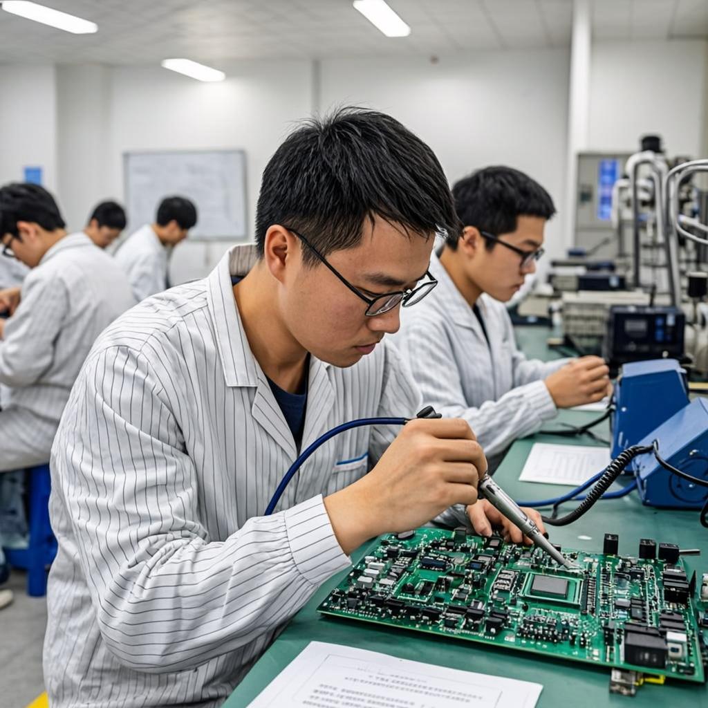
Assembly adds another layer of complexity. Most medical PCBs combine SMT (Surface Mount Technology) and through-hole components, requiring careful process sequencing.
Surface mount dominates modern medical electronics for good reasons—smaller footprints, better high-frequency performance, and automated placement accuracy down to 0.01mm. The typical SMT flow:
Despite SMT’s dominance, through-hole remains necessary for:
Selective wave soldering or hand soldering with IPC J-STD-001 certified operators maintains quality while preserving temperature-sensitive SMT components.
Medical PCB assembly typically occurs in ISO Class 7 or Class 8 cleanrooms. Higher-risk implantable devices may require ISO Class 6 environments. Cleanroom practices include:
Navigating medical device regulations requires understanding multiple overlapping standards from different governing bodies.
Class 3 represents the highest reliability tier. For medical PCBs, this means:
Manufacturers selling medical devices in the United States must:
Medical PCBs serve virtually every area of modern healthcare:
Your manufacturing partner can make or break a medical device program. Evaluate potential suppliers against these criteria: