If you’re looking to build a custom electric motor drive PCB for precise motor control, you’ve come to the right place. Whether it’s for a DIY project, a robotics application, or an industrial system, designing a unique motor drive PCB can seem daunting. But with the right steps, tools, and know-how, you can create a reliable and efficient board tailored to your needs. In this comprehensive guide, we’ll walk you through the entire process of custom PCB design for motor control, from planning to testing, ensuring you have actionable insights for success.
Custom electric motor drive PCBs offer unmatched flexibility compared to off-the-shelf solutions. By designing your own board, you can optimize for specific voltage ranges, current capacities, and control algorithms. This is especially useful for applications like drones, electric vehicles, or automated machinery where space, efficiency, and performance are critical. For instance, a tailored motor driver PCB can handle high currents—up to 50A or more—while maintaining compact dimensions as small as a credit card.
Beyond performance, building a custom PCB motor driver allows you to integrate unique features like sensor feedback or wireless control, which generic boards might not support. Plus, it’s a cost-effective solution for bulk production or specialized projects. Let’s dive into the step-by-step process of creating your own motor control PCB.
Before you start designing, clarify the purpose and specifications of your motor drive PCB. Consider the type of motor you’re controlling—DC, brushless DC (BLDC), or stepper—and the operational needs. Here are key factors to outline:
For example, a BLDC motor for a drone might need a PCB that supports 24V input, 20A continuous current, and PWM control for variable speed. Writing down these specs ensures you don’t overlook critical details during design.
Choosing components is a critical step in designing a unique motor drive PCB. Each part must align with your specs to ensure reliability and performance. Here’s what to focus on:
Double-check datasheets for thermal limits and compatibility. A mismatched component can lead to overheating or failure. For instance, using a MOSFET with insufficient current handling can cause a short circuit under load.
With components selected, it’s time to draft a schematic—a blueprint of how everything connects. Use PCB design software to draw your circuit. Focus on these aspects:
For noise reduction, place decoupling capacitors (e.g., 0.1μF ceramic) close to the MCU’s power pins. This prevents voltage drops during sudden current demands. Once your schematic is ready, simulate it if possible to catch errors before moving to layout.
The PCB layout turns your schematic into a physical board. A well-designed layout minimizes noise, heat, and signal loss. Follow these tips for success:
Pay attention to component placement. Group related parts (e.g., driver IC and MOSFETs) close together to shorten trace lengths. A compact layout also saves space and reduces parasitic inductance, which can cause voltage spikes at high frequencies.
The materials and layer stack-up of your PCB impact durability and performance. For motor control applications, consider these options:
For example, a 4-layer board with 2oz copper can handle 40A currents with less risk of overheating compared to a 2-layer, 1oz design. Consult with your manufacturing partner to balance cost and performance based on your needs.
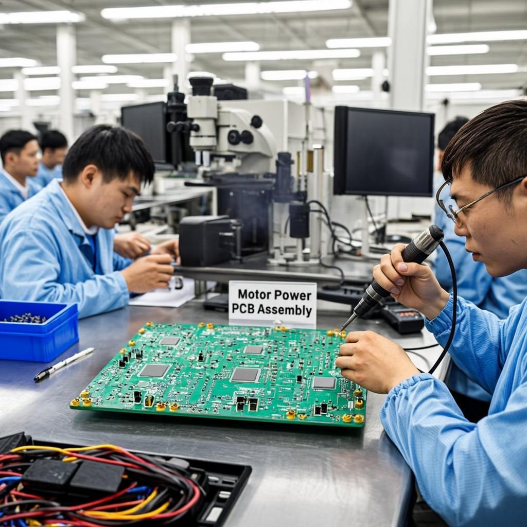
Once your design is complete, order a prototype to validate its functionality. Testing is crucial before full production. Follow these steps:
If issues arise, such as overheating or signal glitches, revisit your layout or component choices. Iterating on prototypes is normal for perfecting a custom PCB motor driver.
After successful testing, prepare your design for manufacturing. Optimize for cost and scalability with these tips:
Work closely with your PCB manufacturer to finalize details like surface finish (e.g., ENIG for durability) and solder mask color. Clear communication prevents delays or errors during production.
Even with careful planning, challenges can arise when building a custom PCB motor driver. Here are common issues and how to address them:
Anticipating these problems during the design phase saves time and resources. For instance, adding extra vias for heat dissipation during layout can prevent thermal issues later.
Designing a custom electric motor PCB is easier with the right tools. Here are some categories of resources to explore:
Additionally, online communities and forums provide tutorials and advice for beginners. Learning from others’ experiences can accelerate your progress in creating a custom motor control board.
Designing a custom electric motor drive PCB is a rewarding process that empowers you to create tailored solutions for your projects. By following this step-by-step guide—defining requirements, selecting components, creating schematics, laying out the board, and testing prototypes—you can build a reliable and efficient motor driver. Whether you’re working on a DIY motor control PCB or a professional application, attention to detail and iterative testing are key to success.
With the right approach, you can overcome challenges like heat management and EMI, ensuring your board performs as intended. Partner with a trusted PCB manufacturing service to bring your design to life, and don’t hesitate to refine your skills through practice. Start your journey in custom PCB design for motor control today, and unlock endless possibilities for innovation.