In today's electronics world, space is shrinking, while complexity and functionality are growing. Devices like foldable phones, wearable trackers, and smart medical instruments demand circuit boards that are flexible in form but rigid in performance.
Enter the rigid-flex PCB—a hybrid PCB that integrates both rigid and flexible layers into a single unified structure. This allows engineers to design compact, durable, and highly reliable circuits that can bend, fold, or twist without breaking.
In this article, we'll explore the technical foundation of rigid-flex PCBs, their real-world applications, design tips, common pitfalls, and walk through the design of a basic rigid-flex board.
A rigid-flex PCB is essentially a flexible PCB laminated with FR4 PCB outer layers. After lamination, the unwanted areas in the FR4 PCB layers are laser cut to go off and expose the polyimide flexible inner layers.
It combines traditional FR4-based rigid circuits with polyimide-based flexible circuits in a layered configuration. Unlike using separate flex cables and connectors to bridge rigid boards, a rigid-flex PCB is fabricated as a single unit, with copper traces extending seamlessly across both rigid and flexible layers.
Benefits of rigid-flex PCBs:
Microvias penetrate only one rigid layer, so they are laser drilled and electroplated on the rigid layer before the lamination process. The positioning has to be highly precise. Therefore, HDI rigid-flex PCB manufacturing has a high scrap rate, and the board prices are higher than flexible PCBs and normal PCBs.
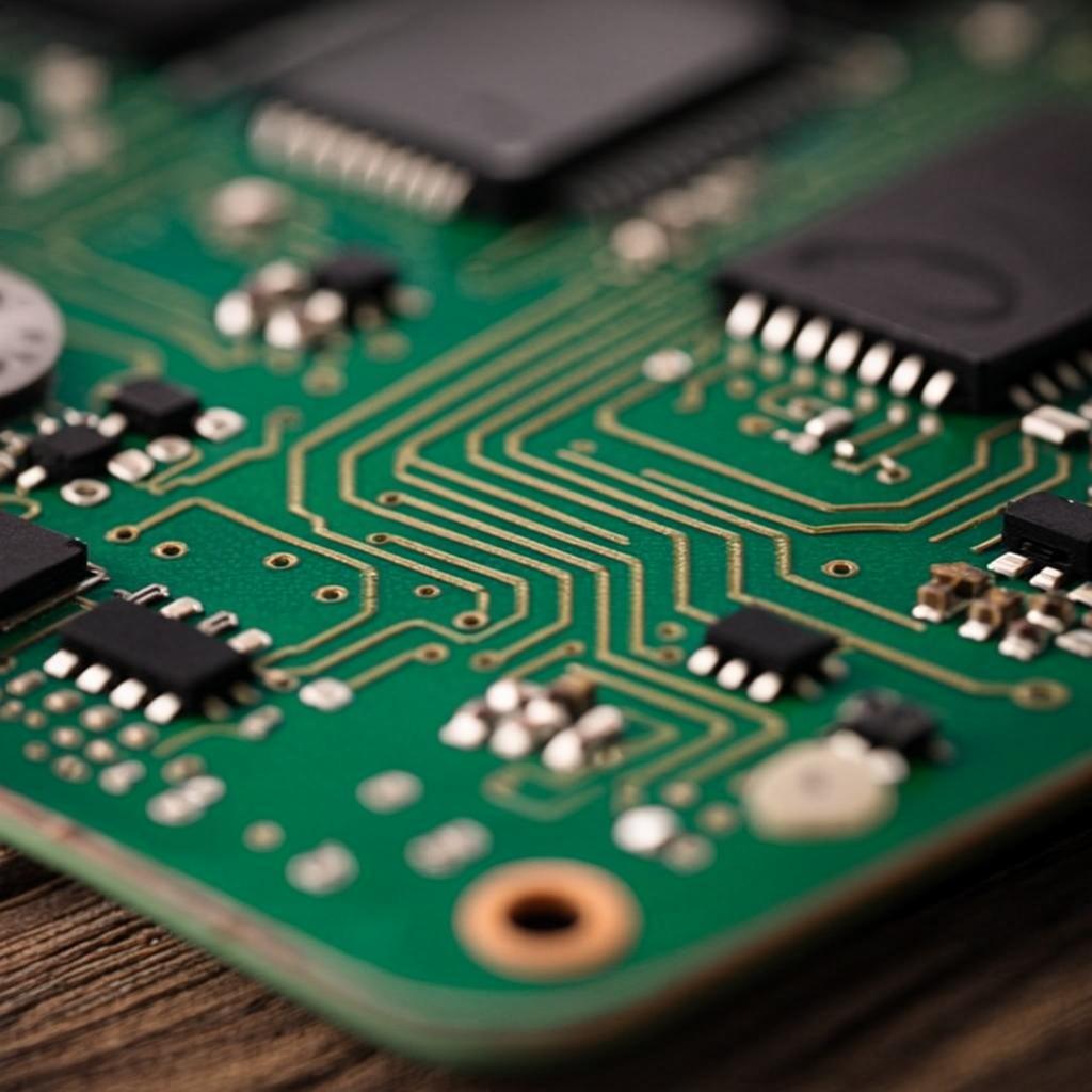
A rigid-flex PCB includes:
A typical stack-up of a 6-layer rigid-flex PCB is 2F6R as below.
A typical stack-up of an 8-layer rigid-flex PCB is 4F8R. You can view its layers, dielectric materials, and their thicknesses:
Rigid-flex PCBs combine the best of both rigid and flexible circuit technologies, enabling high-performance, space-saving, and mechanically robust electronic designs. Their growing popularity across consumer electronics, medical, aerospace, and automotive industries is driven by their ability to reduce interconnects, enhance reliability, and fit into compact or dynamic enclosures.
The applications of rigid-flex PCBs are below.
When designing a rigid-flex PCB, it's easy to fall into traps that can lead to performance issues or fabrication failures. Designing rigid-flex circuits requires careful planning to avoid common pitfalls like incorrect bend radii, inadequate stack-ups, or improper material choices.
Here's what to watch out for:
Avoid 90° or tight bends. These can cause copper to crack. Use gradual bends with a minimum bend radius of 10x the flex thickness.
Tip: Use curved traces and soft corners.
Placing vias in the flex part can lead to stress fractures during bending. Avoid them unless specialized stacked or staggered vias are supported by your manufacturer.
Tip: Keep all vias in rigid zones.
If you mount components on a flexible area without a stiffener (reinforcement layer), the area can flex during operation or soldering, damaging solder joints.
Tip: Apply stiffeners under components in the flex region.
Standard FR4 and polyimide expand and contract differently. Improper selection of adhesive or copper weight can lead to delamination or warping.
Tip: Follow your fab house's rigid-flex material guidelines.
Traces should be routed perpendicular to the bending axis to reduce mechanical stress on copper.
Tip: Use teardrop pads and curved routing in flex areas.
Tip: Use the Layer Stack Manager in the PCB design tool to define rigid and flex layers clearly.
Add components.
If you are looking for turnkey electronic manufacturing for your rigid-flex project, you can PCBONLINE is a leading rigid-flex PCB manufacturer in China that serves clients around the world. You can order rigid flex PCB manufacturing, assembly, and components altogether from PCBONLINE from prototyping to large-scale manufacturing. PCBONLINE is a recommended rigid flex PCB manufacturer for these reasons:
Why choose PCBONLINE for your rigid-flex PCB manufacturer?
PCBONLINE has powerful rigid-flex PCB capabilities, such as 2-24 layers, HDI 4+N+4, FR4/PI/steel stiffeners.
PCBONLINE offers a free DFM review before production to ensure the manufacturability of the rigid-flex PCB stackup and solve any technical issues.
Our experienced R&D and engineering team provides one-on-one engineering support throughout the project, including rigid-flex PCB stackup optimization.
Turnkey OEM rigid-flex PCB services, including prototyping, PCB fabrication, components, rigid-flex PCB assembly, tests, enclosures, box-build assembly, and value-added services.
High-quality rigid-flex PCB manufacturing certified with ISO 9001:2015, ISO 14001:2015, IATF 16949:2016, RoHS, REACH, UL, and IPC-A-600 Class 2/3.
When your rigid-flex project enters the bulky production stage, PCBONLINE refunds the fees of R&D, prototyping, and PCBA functional testing.
Please take a look at PCBONLINE's capabilities in rigid-flex PCB manufacturing:
Please feel free to contact PCBONLINE via email at pcb@frankenthalerfoundation.org or register to get an online quote if you have any needs.
As the demand for smaller, lighter, and more durable devices continues to rise, rigid-flex PCBs are becoming an essential part of modern electronics. By understanding their structure, design guidelines, and real-world applications, engineers can fully leverage their potential. PCBONLINE is a reliable rigid-flex PCB manufacturer providing one-on-one engineering support and turnkey electronics manufacturing. If you want to order or consult about rigid flex PCBs, don't hesitate to contact PCBONLINE.