If you're new to electronics design and wondering how to create an FR-4 PCB prototype, you're in the right place. FR-4 PCB prototyping is the process of designing and building a test version of a printed circuit board using FR-4 material, a popular and cost-effective choice for many applications. In this guide, we'll walk you through the entire FR-4 PCB prototyping process step by step, from design to assembly, ensuring you have the knowledge to bring your ideas to life.
Whether you're working on a hobby project or developing a product for market, understanding the FR-4 PCB prototype manufacturing process is key to success. Let’s dive into the details of FR-4 PCB prototype design, manufacturing, assembly, and more, tailored for beginners with actionable tips and clear explanations.
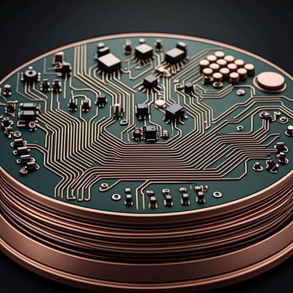
FR-4 is a type of material used in printed circuit boards (PCBs). It stands for "Flame Retardant 4" and is made of woven fiberglass cloth with an epoxy resin binder. This combination makes FR-4 strong, lightweight, and resistant to heat and moisture, which is why it’s the go-to choice for most PCB projects.
For beginners, FR-4 is ideal because it’s affordable and widely available. It supports a variety of applications, from simple single-layer boards to more complex multi-layer designs. Its dielectric constant, typically around 4.5, ensures stable electrical performance, making it suitable for frequencies up to several gigahertz. Additionally, FR-4 can handle temperatures up to 130°C without degrading, which is more than enough for most consumer electronics.
Prototyping with FR-4 material offers several advantages:
With these benefits in mind, let’s explore the step-by-step FR-4 PCB prototyping process to help you create a functional prototype.
The FR-4 PCB prototyping process involves several stages, each critical to ensuring your board works as intended. Below, we break it down into manageable steps for beginners.
Before diving into design, take time to outline what your PCB needs to do. Consider the following:
Having a clear plan reduces errors during the FR-4 PCB prototype design phase and saves time later.
The next step in the FR-4 PCB prototyping process is designing a schematic—a blueprint of how components connect electrically. Use design software to draw your circuit. Popular tools are widely available and often free for basic use.
In your schematic, include all components like resistors, capacitors, and ICs, and define their connections. Double-check values and connections to avoid mistakes. For instance, ensure a resistor’s value matches your calculations—say, 220 ohms for an LED circuit with a 5V supply to limit current to around 20mA.
Once your schematic is ready, convert it into a physical layout. This involves placing components on a virtual board and routing traces (conductive paths) between them. Keep these tips in mind for FR-4 PCB prototype design:
FR-4’s properties, like its dielectric constant of 4.5, help maintain signal integrity during layout, especially for beginners working on low to medium-speed circuits.
After finalizing your layout, export it as Gerber files—a standard format used in FR-4 PCB prototype manufacturing. These files include layers for copper traces, solder mask, silkscreen, and drill holes. Most design tools have built-in options to generate these files.
Check your Gerber files using a viewer tool to ensure there are no errors, such as missing traces or misaligned layers. This step is crucial before sending your design to a manufacturer for FR-4 PCB prototyping services.
Selecting a reliable provider for FR-4 PCB prototyping services is vital. Look for a service that offers:
Submit your Gerber files along with specifications like board thickness and layer count. Many services provide instant quotes based on these details, making budgeting easier for beginners.
Once your files are with the manufacturer, the FR-4 PCB prototype manufacturing process begins. Here’s a simplified overview of what happens:
This process ensures your FR-4 PCB prototype matches your design and is ready for assembly.
With your bare FR-4 PCB in hand, it’s time for assembly—placing and soldering components onto the board. For beginners, manual assembly is common for small projects. Follow these steps:
For larger or complex designs, consider professional FR-4 PCB prototype assembly services. These use automated pick-and-place machines for accuracy and speed, especially for surface-mount components with pitches as small as 0.5mm.
Testing is a critical part of the FR-4 PCB prototyping process. Power up your board and check for functionality. Use a multimeter to verify voltages at key points—for instance, ensure a 5V regulator outputs close to 5V, within a tolerance of ±0.1V.
Beginners often face hurdles during FR-4 PCB prototype manufacturing and assembly. Here are some common issues and solutions:
To make your FR-4 PCB prototyping journey smoother, keep these tips in mind:
FR-4 PCB prototyping is an exciting and accessible way to bring your electronic ideas to life. By following this step-by-step guide, you’ve learned the essentials of the FR-4 PCB prototyping process, from design and manufacturing to assembly and testing. With FR-4’s affordability, durability, and versatility, it’s the perfect material for beginners to experiment and innovate.
Whether you’re creating a small hobby project or laying the groundwork for a larger product, mastering FR-4 PCB prototype design and manufacturing opens up endless possibilities. Take the first step by defining your project requirements and exploring reliable FR-4 PCB prototyping services to turn your vision into reality.